Extracting a Gameboy cartridge ROM
in Posts / Retrocomputing, binary analysis, hardware on Rom, Gameboy, Gb, Gameboycolor, Gbc, Extraction
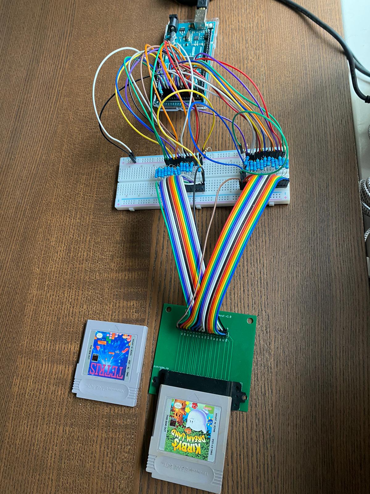
Table of contents
This is the first entry of a Gameboy Hacking series. This post describes how an Arduino was used to extract the ROM code of a GameBoy/Gameboy Color ROM cartridge.
Resources
Software
| Resource | Information |
|---|---|
| Arduino code | GameBoyAnalysis/ROMReader/Arduino/GBRomReader.ino |
| Host control code | GameBoyAnalysis/ROMReader/Host/Reader-Utils.psm1 |
Hardware
| Resource | Image |
|---|---|
| Arduino Mega |  |
| Cartridge reader |  |
| Cartridge breakout board (Optional) |  |
An Arduino UNO can be used as well, adapting the pins with shift registers.
Introduction
Either to use emulators to play the ROMs from your GameBoy cartridges or to modify those ROMs, the first step is always to extract the ROM from the cartridges.
While there are cart readers you might get from an online store, it might take a while to be shipped, and most of them can’t be modified. Therefore, sometimes it is preferable to do it with simple hardware that one might have at hand or that is simple to get online (See the hardware list above).
Hardware setup
Gameboy Cartridge
The GameBoy Cartridge is effectively implemented as a parallel bus. Meaning that there are 16 connections exclusively dedicated as inputs (address pins) and 8 connections as outputs (data pins). This makes for 24 of the 32 lines to the cartridge. The remaining lines consist of ground, voltage, clock, chip select, read control, write control, reset, and audio out.
The full pinout is the following:
| Pin # | Name | Description | Pin # | Name | Description | |
|---|---|---|---|---|---|---|
| 1 | VCC | +5 VDC | 17 | A11 | Address 11 | |
| 2 | PHI | Clock | 18 | A12 | Address 12 | |
| 3 | /WR | Write | 19 | A13 | Address 13 | |
| 4 | /RD | Read | 20 | A14 | Address 14 | |
| 5 | /CS | SRAM select | 21 | A15 | Address 15 | |
| 6 | A0 | Address 0 | 22 | D0 | Data 0 | |
| 7 | A1 | Address 1 | 23 | D1 | Data 1 | |
| 8 | A2 | Address 2 | 24 | D2 | Data 2 | |
| 9 | A3 | Address 3 | 25 | D3 | Data 3 | |
| 10 | A4 | Address 4 | 26 | D4 | Data 4 | |
| 11 | A5 | Address 5 | 27 | D5 | Data 5 | |
| 12 | A6 | Address 6 | 28 | D6 | Data 6 | |
| 13 | A7 | Address 7 | 29 | D7 | Data 7 | |
| 14 | A8 | Address 8 | 30 | /RST | Reset | |
| 15 | A9 | Address 9 | 31 | AUDIO | Audio (Rarely used) | |
| 16 | A10 | Address 10 | 32 | GND | Ground |
Note: / Denotes an active low pin.
Note: The Cartridge reader has incorrect labeling of the pins. It is helpful to use the Cartridge breakout board as a reference by connecting it to the reader, which allows to probe and identify the lines (as the breakout board has correct labeling).
Line connections
From the perspective of the cartridge, some pins are floating and require a pull up/down resistor to enforce a known state, in this case, 10K Ohm resistors were used. Also, smaller resistors (470 Ohm) were occupied in all the control and data lines to protect the Gameboy cartridge MCU (this is usually recommended and depends on the maximum current draw specifications).
The following schematic shows how these resistors were placed and the connections between the Cartridge reader and Arduino Mega, please note that the pin labeling in the cartridge reader is incorrect.

Software
Overview
There are different hardware configurations of Gameboy cartridges. Some of them have a Memory Controller, others have RAM banks, and some only ROM. A comprehensive table can be found in section 1.4. of this document. In terms of the software implementation of the ROM reader, the focus was on supporting “ROM only” and “ROM+MBC1” type cartridges, but the design was left open to support other cartridge types.
The implementation consists of a host-side API written in Powershell that communicates over a serial bus with an Arduino Mega. The Arduino is given a bank and an address to read from, then after receiving this message, it will respond by reading 4 bytes from that location and sending it back to the host through the serial connection.

Memory access
Memory layout
Gameboy and Gameboy Color run an 8-bit processor, with a 16-bit addressing memory bus. This means that the addressing space is 64KB long. The addressing space is used for multiple purposes such as MMIO (Memory Mapped IO), RAM, and ROM.
The memory map of a Gameboy is specified as the following:
| Address range | Description |
|---|---|
| 0xFFFF | Interrupt Enable Flag |
| 0xFF80-0xFFFE | Zero Page - 127 bytes |
| 0xFF00-0xFF7F | Hardware I/O Registers |
| 0xFEA0-0xFEFF | Unusable Memory |
| 0xFE00-0xFE9F | OAM - Object Attribute Memory |
| 0xE000-0xFDFF | Echo RAM - Reserved, Do Not Use |
| 0xD000-0xDFFF | Internal RAM - Bank 1-7 (switchable - CGB only) |
| 0xC000-0xCFFF | Internal RAM - Bank 0 (fixed) |
| 0xA000-0xBFFF | Cartridge RAM (If Available) |
| 0x9C00-0x9FFF | BG Map Data 2 |
| 0x9800-0x9BFF | BG Map Data 1 |
| 0x8000-0x97FF | Character RAM |
| 0x4000-0x7FFF | Cartridge ROM - Switchable Banks 1-xx |
| 0x0150-0x3FFF | Cartridge ROM - Bank 0 (fixed) |
| 0x0100-0x014F | Cartridge Header Area |
| 0x0000-0x00FF | Restart and Interrupt Vectors |
Some games might need more ROM or RAM than the 64KB memory space can provide, in order to overcome this limitation some cartridge memory controllers allow to map and switch between different banks of ROM (and RAM in Gameboy Color) to a predefined memory region (0x4000-0x7FFF in case of ROM, 0xD000-0xDFFF for RAM).
This article focuses on extracting the ROM memory. To do so, it is necessary to traverse all of the ROM’s memory banks. To switch between banks a write instruction containing the index of the desired bank can be issued into any address of the ROM memory space 0x0150 - 0x3FFF (for example writing 0x2 into 0x2100 will switch to bank 2).
Crafting a read command
To perform a read from the cartridge, the read mode should be set. This can be done by asserting the “Read” line and de-asserting the “Write” line (these are active low pins).
// Set to Read Mode
digitalWrite(GAMEBOY_RD, LOW);
digitalWrite(GAMEBOY_WT, HIGH);
Then the desired address to be read needs to be set in the address pins.
void writeAddress(uint16_t address)
{
    // Write each of the bits into the address pins
    for (uint32_t i = 0; i < sizeof(ADDRESS_PINS)/sizeof(ADDRESS_PINS[0]); i++)
    {
        digitalWrite(ADDRESS_PINS[i], address & (1 << i) ? HIGH : LOW);
    }
}
After setting the address to read from, the data pins are queried to get the stored value.
uint8_t readData()
{
    uint8_t data = 0;

    // Read each of the data pins and construct the byte data
    for (uint32_t i = 0; i < sizeof(DATA_PINS)/sizeof(DATA_PINS[0]); i++)
    {
        data |= digitalRead(DATA_PINS[i]) << i;
    }

    return data;
}
Switching banks
As mentioned previously, some cartridges might possess more than one ROM bank. To traverse additional banks it is possible to switch between them by issuing a write instruction into the ROM memory space.
void selectBank(uint32_t bank)
{
    // Set to write mode
    digitalWrite(GAMEBOY_RD, HIGH);
    digitalWrite(GAMEBOY_WT, LOW);

    // Change the pin typing
    for (uint32_t i = 0; i < sizeof(DATA_PINS)/sizeof(DATA_PINS[0]); i++)
    {
        pinMode(DATA_PINS[i], OUTPUT);
    }

    // Write the bank address
    writeAddress(BANK_SWITCH_ADDRESS);

    delay(5);

    // Write the bank to switch to
    for (uint32_t i = 0; i < sizeof(DATA_PINS)/sizeof(DATA_PINS[0]); i++)
    {
        digitalWrite(DATA_PINS[i], bank & (1 << i) ? HIGH : LOW);
    }

    delay(5);

    digitalWrite(GAMEBOY_RD, LOW);
    digitalWrite(GAMEBOY_WT, HIGH);

    // Set the data to LOW
    for (uint32_t i = 0; i < sizeof(DATA_PINS)/sizeof(DATA_PINS[0]); i++)
    {
        digitalWrite(DATA_PINS[i], LOW);
    }

    // Set pins back as inputs
    for (uint32_t i = 0; i < sizeof(DATA_PINS)/sizeof(DATA_PINS[0]); i++)
    {
        pinMode(DATA_PINS[i], INPUT);
    }

    delay(5);
}
Enabling Serial communication
It would be possible to create an Arduino program to dump the whole ROM. In this case, to facilitate the debugging and to allow for more flexibility (by sacrificing some performance), the Arduino program will interface through a Serial connection with the connected host machine, where a simple protocol will allow the host computer to request 4 bytes by sending a bank and an address.
Opening a serial connection
The serial connection is done through the USB port that is connected from the Arduino to the host machine (in this case the same that it is used to flash the Arduino). To set up the Arduino to enable the Serial connection, the following line is issued during the setup:
#define SERIAL_BAUD_RATE 115200
...
void setup()
{
...

    // Start serial connection to host
    Serial.begin(SERIAL_BAUD_RATE);
}
Similarly from the host side, a connection needs to be established:
Function Open-GB($Com)
{
    $global:port = new-Object System.IO.Ports.SerialPort $Com,115200,None,8,one
    $global:port.open()

    for ($k = 0; $k -lt 4; $k++)
    {
        # There are four 0 bytes initially, clear them from the connection
        $global:port.ReadByte() | Out-Null
    }
}
Requesting data from the Arduino
Now that the connection is set up, the sender and the receiver side will agree on how data is transmitted. For this case, a simple synchronous message will be initiated from the host where a bank and address is specified, and in return, the Arduino will respond with the 4 bytes stored in the given address to address + 3.
The host will request an address:
Function Read-Address($Address)
{
    $global:port.Write([BitConverter]::GetBytes([UInt32]$Address), 0, 4);

    for ($k = 0; $k -lt 4; $k++)
    {
        [String]::Format("{0:X02}", $global:port.ReadByte())
    }
}
The Arduino responds with:
void loop()
{
    uint32_t input = 0;
    uint32_t selectedBank = currentBank;
    uint16_t selectedAddress = 0;

    uint8_t data = 0;

    // Set to Read Mode
    digitalWrite(GAMEBOY_RD, LOW);
    digitalWrite(GAMEBOY_WT, HIGH);

    // Get request from host
    while(!Serial.available()){}
    Serial.readBytes((uint8_t*)&input, sizeof(uint32_t));

    selectedAddress = (uint16_t) input & 0xFFFF;
    selectedBank = (input >> 16) + 1;

    // If we are reading from the banked rom range, make sure
    // we are in the appropiate bank
    if (selectedAddress >= 0x4000 && currentBank != selectedBank)
    {
        selectBank(selectedBank);
        currentBank = selectedBank;
    }

    // Read 4 bytes of data
    for (uint32_t i = 0; i < sizeof(uint32_t); i ++)
    {
        writeAddress(selectedAddress + i);
        delay(5);
        data = readData();
        // Send response
        Serial.write((uint8_t *)&data, 1);
    }
}
Now that both sides are communicating. It is possible to validate the correctness by reading a known address and comparing the output. In the case of the Gameboy, each cartridge stores the Nintendo logo at a fixed address. By adding more logic it is possible to enable Powershell to read a bigger range of memory, that can be useful for validating our test case:
Function Read-Range($Start, $Length)
{
    for ($i = $Start; $i -lt $Start + $Length; $i+=4)
    {
        Write-Host ((Read-Address $i) + " ") -NoNewLine

        if (($i - $Start) % 16 -eq 12)
        {
            Write-Host ""
        }
    }
}
This function is used to read the section containing the Nintendo logo (at 0x104):
Read-Range -Start 0x104 -Length 48
CE ED 66 66  CC 0D 00 0B  03 73 00 83  00 0C 00 0D
00 08 11 1F  88 89 00 0E  DC CC 6E E6  DD DD D9 99
BB BB 67 63  6E 0E EC CC  DD DC 99 9F  BB B9 33 3E
Which matches the expected output, based on the information [here] (https://gbdev.gg8.se/wiki/articles/The_Cartridge_Header#0104-0133_-_Nintendo_Logo):
CE ED 66 66 CC 0D 00 0B 03 73 00 83 00 0C 00 0D
00 08 11 1F 88 89 00 0E DC CC 6E E6 DD DD D9 99
BB BB 67 63 6E 0E EC CC DD DC 99 9F BB B9 33 3E
Extracting the ROMs from a Gameboy and a Gameboy Color cartridge
Cartridge capabilities
As stated previously, there are various types of Gameboy cartridges, that possess different capabilities. In order to discover those, each cartridge has a header containing vendor information and a description of the cartridge. Detailed information about the cartridge header can be found here. For dumping a ROM the address of interest are 0x0147 (Cartridge type)and 0x0148 (ROM size).
Cartridge Type (0x0147)
| Value | Type |
|---|---|
| 0x00 | ROM ONLY |
| 0x01 | MBC1 |
| 0x02 | MBC1+RAM |
| 0x03 | MBC1+RAM+BATTERY |
| 0x05 | MBC2 |
| 0x06 | MBC2+BATTERY |
| 0x08 | ROM+RAM |
| 0x09 | ROM+RAM+BATTERY |
| 0x0B | MMM01 |
| 0x0C | MMM01+RAM |
| 0x0D | MMM01+RAM+BATTERY |
| 0x0F | MBC3+TIMER+BATTERY |
| 0x10 | MBC3+TIMER+RAM+BATT |
| 0x11 | MBC3 |
| 0x12 | MBC3+RAM |
| 0x13 | MBC3+RAM+BATTERY |
| 0x19 | MBC5 |
| 0x1A | MBC5+RAM |
| 0x1B | MBC5+RAM+BATTERY |
| 0x1C | MBC5+RUMBLE |
| 0x1D | MBC5+RUMBLE+RAM |
| 0x1E | MBC5+RUMBLE+RAM+BATTERY |
| 0x20 | MBC6 |
| 0x22 | MBC7+SENSOR+RUMBLE+RAM+BATTERY |
| 0xFC | POCKET CAMERA |
| 0xFD | BANDAI TAMA5 |
| 0xFE | HuC3 |
| 0xFF | HuC1+RAM+BATTERY |
Rom Size
| Value | Rom size |
|---|---|
| 0x00 | 32KByte (no ROM banking) |
| 0x01 | 64KByte (4 banks) |
| 0x02 | 128KByte (8 banks) |
| 0x03 | 256KByte (16 banks) |
| 0x04 | 512KByte (32 banks) |
| 0x05 | 1MByte (64 banks) - only 63 banks used by MBC1 |
| 0x06 | 2MByte (128 banks) - only 125 banks used by MBC1 |
| 0x07 | 4MByte (256 banks) |
| 0x08 | 8MByte (512 banks) |
| 0x52 | 1.1MByte (72 banks) |
| 0x53 | 1.2MByte (80 banks) |
| 0x54 | 1.5MByte (96 banks) |
Reading the Rom
As an example, the cartridge for Kirby’s DreamLand will be dumped. As mentioned above, to properly read a cartridge it is required to know its capabilities. For this the addresses 0x147 and 0x148 will be queried:
(Read-Address -Address 0x147)[0]
01
(Read-Address -Address 0x148)[0]
03
From this information, it is possible to conclude that this cartridge is an MCB1 with 16 ROM banks (256KByte ROM).
To dump the complete cartridge additional logic was added to the Powershell scripts, which will traverse the different banks and request for the data.
Function Read-Rom($MemoryBankNumber)
{
    $TotalBytes = 0x4000 * $MemoryBankNumber
    $CurrentBytes = 0

    $ByteArray = [System.Byte[]]::new($TotalBytes)

    # Read bank 0
    for ($i = 0; $i -lt 0x4000; $i += 4)
    {
        $global:port.Write([BitConverter]::GetBytes([UInt32]$i), 0, 4) | Out-Null

        for ($k = 0; $k -lt 4; $k++)
        {
            $ByteArray[$CurrentBytes] = $global:port.ReadByte()
            $CurrentBytes ++;
        }

        if ($i % 0x200 -eq 0)
        {
            Write-Progress -Activity "Dumping ROM" -PercentComplete (($CurrentBytes/$TotalBytes) * 100)
        }
    }

    # Read all other banks
    for ($Bank = 0; $Bank -lt $MemoryBankNumber -1; $Bank++)
    {
        for ($i = 0x4000; $i -lt 0x8000; $i += 4)
        {
            $Address = ($Bank -shl 16) -bor $i
            $global:port.Write([BitConverter]::GetBytes([UInt32]$Address), 0, 4) | Out-Null

            for ($k = 0; $k -lt 4; $k++)
            {
                $ByteArray[$CurrentBytes] = $global:port.ReadByte()
                $CurrentBytes ++;
            }

            if ($i % 0x200 -eq 0)
            {
                Write-Progress -Activity "Dumping ROM" -PercentComplete (($CurrentBytes/$TotalBytes) * 100)
            }
        }
    }

    return $ByteArray
}
By calling this function, the bytes can be stored in a variable to do validation, manipulation, or storing into a file (This might take some time as it only reads 4 bytes at a time):
$Bytes = Read-Rom -MemoryBankNumber 16
    Dumping ROM
    Processing
    [oooo                                                                      ]

Set-Content -Path "KirbyDreamland.gb" -Value $Bytes -Encoding Byte
After extracting the content, a hex editor was used to review its content:

That file can be used in an emulator to verify it is correct:

Moreover, a Gameboy Color ROM was extracted from its cartridge. For this example, The Mummy cartridge was used: 
After extracting the bank 0 and looking at the header of the ROM (0x147-0x148) it was possible to observe that this cartridge is an MBC5 (0x19) and it has 64 banks (0x05)
$Bytes = Read-Rom -MemoryBankNumber 64
    Dumping ROM
    Processing
    [oooo                                                                      ]

Set-Content -Path "TheMummy.gbc" -Value $Bytes -Encoding Byte
Similarly, the extracted file was opened with a hex editor to review its content: 
Finally, this file was ran in an emulator to verify it was extracted correctly:
